

The most popular advice about data center redundancy is simple: buy 2N, call it resilient, and move on. That advice fails in production. A duplicated power path can still share a switchboard, a PDU, a maintenance procedure, or an operator mistake.
For a Proxmox cluster, start by verifying that every node sees both power paths and that the cluster can evacuate or restart workloads before you trust the design:
pvecm status
ha-manager status
ipmitool chassis power status
ipmitool sel elist
Then pull one feed, not both, and confirm that the node stays online, Corosync remains healthy, and the affected virtual machines recover as designed. More hardware isn't automatically more uptime. The right design matches the failure modes your workload can tolerate, the operational work your team can perform, and the cost of an outage.
Table of Contents
- What Data Center Redundancy Means
- The Three Layers of Redundancy
- Tier Levels and How They Map to Uptime
- Redundancy Topologies From N to 2N+1
- Implementing Redundancy in a Real Environment
- Why 2N Sites Still Go Down
- Testing, Monitoring, and Operational Discipline
- Right-Sizing Redundancy for Your Workload
What Data Center Redundancy Means
Data center redundancy adds duplicate capacity, independent paths, or separate sites so one failure does not interrupt a workload. Examples include dual server power supplies, N+1 cooling units, separate A and B electrical paths, multiple network routes, replicated storage, and a second facility.
The practical question is not how much hardware you can duplicate. It is which failure your design must absorb. More redundancy isn't always better. Extra equipment increases purchase, maintenance, energy, and operational costs. It also creates more components and procedures to test. A design built far beyond the workload's risk profile can reduce efficiency while retaining a shared upstream device or human error that defeats both supposedly independent paths. Even a 2N site can fail when its failure domains are not separate.
The Uptime Institute tier model provides a useful baseline. Its availability figures rise from 99.671% for Tier I to 99.995% for Tier IV, as summarized in Socomec's data center redundancy overview. Those figures describe facility design requirements, not a promise that duplicated hardware will prevent every outage. Maintenance quality, change control, path isolation, and tested recovery still determine what happens in production.
Start with the failure you need to absorb
Write down the failure that matters before choosing a tier:
- A single server component failure.
- A UPS module or cooling unit failure.
- Maintenance on an entire power or cooling subsystem.
- Utility loss affecting the facility.
- A regional event affecting the building itself.
- A software, storage, or operator failure that facility redundancy cannot prevent.
That list changes the buying decision. Dual PSUs help with a failed PSU, but not when both cords terminate on the same PDU. A second UPS helps with a UPS failure only when the distribution paths are independent. A second site addresses a facility event, but it adds replication, application failover, and data-consistency work.
For an SMB, that may mean N+1 capacity and carefully separated power feeds. An enterprise may need maintenance tolerance across larger systems. A managed-hosting buyer may prefer a provider that carries the facility and recovery burden rather than building every layer independently.
Practical rule: Define the failure domain before buying duplicate equipment.
The finished design should identify the topology that supports the SLA, the Uptime Tier that describes the facility requirement, and the operational responsibility your team can sustain. That may point to an N+1 private environment, a Tier III colocation facility, or geographically separated infrastructure for a workload that cannot tolerate a single-site event.
The Three Layers of Redundancy
Redundancy becomes easier to evaluate when you separate it into component, system, and site layers. Each layer catches a different class of failure. Combining them without mapping the failure domains first produces expensive duplication with hidden common points.
Component redundancy
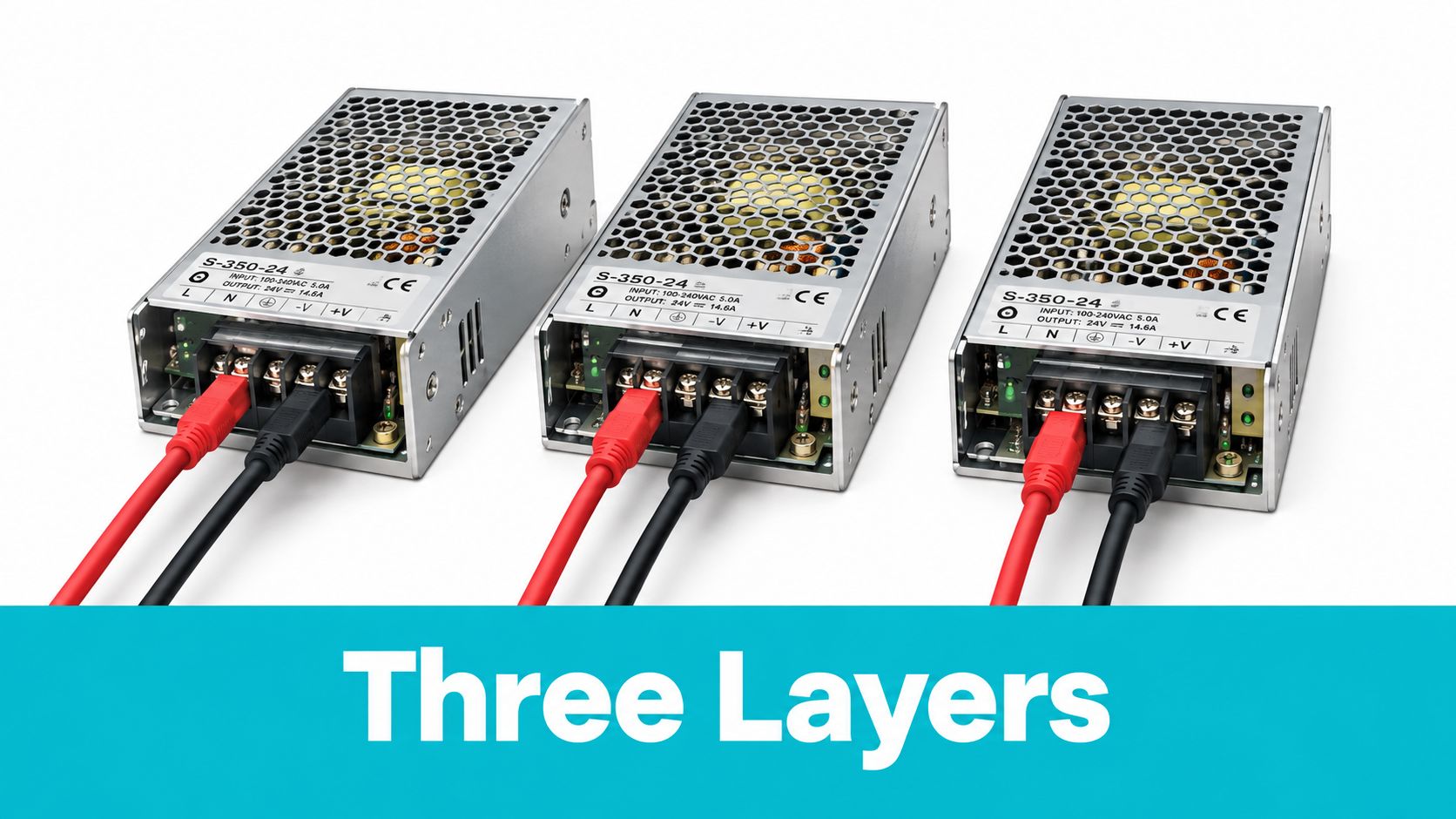
Component redundancy sits inside a chassis or appliance. A server might have dual PSUs, multiple fans, RAID-protected disks, and more than one network interface. If one PSU fails, the other can carry the load, assuming each PSU connects to a different upstream path.
This layer doesn't protect against a failed PDU, a tripped breaker, a switch firmware problem, or a bad change applied to the whole rack. It also doesn't create application failover. A server with two healthy PSUs remains a single server.
System redundancy
System redundancy duplicates a subsystem that serves multiple racks. Examples include UPS modules, generators, switchgear, chillers, pumps, network switches, and fire-control systems. N+1 means the installed capacity includes one additional unit beyond the capacity required for the load. That spare helps absorb a component failure or permit maintenance, but a shared bus or control system can remain a single point of failure.
Consider a failed UPS module. Component redundancy might keep one server online if that server has another PSU. System redundancy can keep the room online if the remaining UPS capacity and distribution bus support the load. A separate site does nothing immediately unless the applications replicate there and can accept traffic.
Site redundancy
Site redundancy places infrastructure in separate facilities or regions. It addresses failures that affect the building rather than a replaceable component, including a utility event, flood, hurricane, carrier disruption, or facility-wide operational mistake.
A Tampa or Florida deployment also needs a location-specific disaster recovery review. Local latency and on-site remote hands may favor a Tampa facility, while a second region may be appropriate for a scenario that could affect the local utility or weather system. Site redundancy is only useful when the database, identity systems, DNS, queues, backups, and traffic routing support the same recovery objective.
| Layer | Protects against | Does not automatically protect against |
|---|---|---|
| Component | PSU, fan, disk, or interface failure | Shared rack power, software failure, operator error |
| System | UPS, generator, chiller, switch, or pump failure | Common bus faults, bad maintenance, facility-wide events |
| Site | Building, utility, regional, or carrier failure | Replication errors, bad releases, corrupted data |
The practical test is simple: trace the load backward from the server to the utility and forward from the server to the user. Mark every shared device and control plane. Those shared points, not the marketing label, define the remaining risk.
Tier Levels and How They Map to Uptime
A higher tier does not automatically produce a more available application. It buys specific facility capabilities, and those capabilities only matter when the workload can use them. Redundancy is a right-sizing decision, not a contest to install the most equipment possible.
Uptime Institute tiers describe how a facility handles maintenance and failure. TIA-942 ratings describe topology mechanics, including distribution paths and fault-tolerant design. The frameworks overlap, but their labels are not interchangeable. The TIA-942 topology overview distinguishes single-path, redundant-component, concurrently maintainable, and fault-tolerant arrangements.
| Level | Uptime Availability | Annual Downtime | Concurrent Maintainability | Fault Tolerance | Typical Topology |
|---|---|---|---|---|---|
| Uptime Institute Tier I | 99.671% | About 28.8 hours | No | No | Single distribution path, no redundant components |
| Uptime Institute Tier II | 99.741% | About 22.7 hours | No | No | Single path with partial redundant components, commonly N+1 components |
| Uptime Institute Tier III | 99.982% | About 1.6 hours | Yes | No | Multiple paths, one active path, N+1 components |
| Uptime Institute Tier IV | 99.995% | About 26.3 minutes | Yes | Yes | Multiple active paths, 2N or 2N+1 style fault tolerance |
| TIA-942 Rated 1 | Framework distinction | Not stated in the supplied data | No | No | Single path and no redundant components |
| TIA-942 Rated 2 | Framework distinction | Not stated in the supplied data | No | No | One path with redundant components |
| TIA-942 Rated 3 | Framework distinction | Not stated in the supplied data | Yes | Not equivalent to full fault tolerance | Multiple paths with one active path and N+1 components |
| TIA-942 Rated 4 | Framework distinction | Not stated in the supplied data | Yes | Yes | Multiple active paths with 2N or 2(N+1) style redundancy |
Treat the annual figures as planning benchmarks, not application guarantees. They describe facility design assumptions. They do not account for database rollback, a failed deployment, corrupted data, or recovery that takes longer than an electrical transfer.
A practical selection starts with the workload:
- Can the business accept planned maintenance downtime?
- Can the application restart on another node without corrupting state?
- Can users be redirected to another site with current data?
An SMB running reproducible development systems may have little reason to pay for the highest facility tier. An enterprise platform with strict maintenance requirements may need a concurrently maintainable design, plus application replication and tested failover. A managed-hosting buyer should verify the provider's paths, maintenance process, power-feed separation, and recovery responsibilities instead of relying on a tier number.
A Tier IV room hosting one unreplicated database still has an application-level single point of failure. A lower-tier facility can serve a workload well when its data is backed up, its systems are reproducible, and its downtime is acceptable.
For a facilities review, compare the requirements in ARPHost's Tier 4 data center requirements guide with the workload's recovery objectives. The tier should support the architecture, not substitute for one.
Redundancy Topologies From N to 2N+1
Redundancy is a sizing decision, not a contest to install the most equipment. The letter N means the capacity required to carry the live load. N+1 adds one spare unit or module. 2N provides two separate systems, each sized for the full load. 2N+1 duplicates that full-capacity design and adds spare capacity on top.
The distinction is practical. A spare module can cover one component failure while the system remains on one bus. A separate 2N path can carry the load after an entire power side fails, provided the A and B paths are electrically and physically independent. Two labels do not create two paths if both sides share a switchboard, control system, or maintenance bypass.
| Topology | Capacity vs Load | Concurrent Maintenance | Cost Premium | Example in 1 MW Room |
|---|---|---|---|---|
| N | Exactly required capacity | No, maintenance may interrupt the load | Lowest | One capacity block sized to the load |
| N+1 | Required capacity plus one spare unit or module | Often, depending on the distribution path | Higher than N, exact premium depends on design | Required cooling or UPS units plus one additional unit |
| 2N | Two independent full-capacity systems | Yes, if paths remain isolated | Substantially higher than N+1 | Two complete A and B power or cooling systems |
| 2N+1 | Two full systems plus spare capacity | Yes, with greater tolerance for maintenance and failure | Highest of these options | Two full systems with additional spare capacity |
These categories describe relative cost, not a fixed surcharge. Equipment selection, floor space, fuel systems, electrical service, controls, commissioning, and capacity installed ahead of demand all change the result. Duplicated equipment also tends to run at lighter loads, which can reduce operating efficiency. More redundancy can therefore increase both capital and ongoing costs without improving the workload's actual recovery capability.
Active-passive and active-active
Active-passive designs place production work on one system while another waits for a failover signal. The model is easier to reason about, but the standby path must be tested. Transfer logic, health checks, and the failover signal become part of the failure domain.
Active-active designs run workload on both systems. They can reduce switchover latency and use installed equipment more efficiently, but they require accurate load balancing, reliable health checks, state management, and failure isolation. A shared configuration mistake can still affect both sides at once.
For a 1 MW critical load, each 2N side must support the full room load. Splitting the load between two undersized sides creates capacity sharing, not 2N redundancy. Apply the same test to generators, UPS output, switchboards, PDUs, chillers, and pumps.
An SMB with a tolerable maintenance window may have no operational reason to fund 2N+1. An enterprise platform with strict maintenance requirements may justify 2N, while a managed-hosting buyer should verify whether the provider's quoted topology includes separate A and B paths. The right topology matches the failure the business can afford, not the largest label available.
A dual-corded server has no independent protection when both cords depend on the same upstream equipment. The required separation between A and B paths is also described in Grundfos' overview of Uptime Institute classifications.
Implementing Redundancy in a Real Environment
A workable implementation starts at the load and moves upstream. Don't begin with a tier label. Begin with the rack diagram, then verify every connection under failure conditions.
Build the power path
- Install dual-corded servers and connect PSU A to PDU A and PSU B to PDU B.
- Feed PDU A and PDU B from electrically independent UPS and distribution paths.
- Verify that the paths remain separate through switchboards, transfer equipment, and generators.
- Add cooling capacity that can carry the required thermal load after the planned failure.
- Document which equipment is allowed to share a breaker, bus, control system, or maintenance bypass.
A server's two cords provide no meaningful protection when both connect to one PDU. The same mistake occurs one level higher when two PDUs sit behind one switchboard. Walk the cable physically, and record the upstream device for every cord.
UPS batteries bridge the gap between utility failure and generator availability. A common UPS operating window is about 5 to 15 minutes at full load, while generator start and transfer are commonly designed around roughly 10 to 15 seconds, with some standards targeting transfer within about 10 seconds, as described in CSE Magazine's UPS and generator guidance. Design the battery bridge around measured load, battery condition, temperature, and generator stabilization, not the nameplate runtime alone.
Add software-layer failover
Facility redundancy doesn't restart a virtual machine on another node. In Proxmox VE, use redundant Corosync networking, quorum-aware cluster design, shared or replicated storage, and fencing. A minimal HA resource command looks like this:
pvecm status
pvecm nodes
ha-manager add vm:201 --state started --max_restart 3 --max_relocate 2
ha-manager status
For a three-node cluster, use separate Corosync links on redundant switches where possible. Confirm that node loss triggers fencing and that the storage layer doesn't expose stale writes. Software HA is only useful when the power, network, and storage layers above it remain available.
Commission before accepting production load
Use a written commissioning checklist:
- Confirm phase loading and investigate imbalance before normal operations.
- Test automatic transfer equipment under controlled conditions.
- Pull each power side independently and verify that the load stays online.
- Confirm IPMI reachability through the B feed.
- Check that alerts identify the failed path rather than only reporting a node outage.
- Validate Proxmox quorum, HA recovery, backup restoration, and application health checks.
In multi-tenant infrastructure, the most revealing test isn't a dashboard turning green. It's a controlled failure that proves tenants keep network access, storage remains consistent, and the operations team knows which breaker or module is safe to touch.
Why 2N Sites Still Go Down
2N doesn't mean failure-proof. The Uptime Institute's 2025 survey found that 42% of respondents used 2N redundant power equipment in their primary data center, while 41% used N+1, according to the Uptime Institute Global Data Center Survey 2025. The 2024 survey also found that 53% of operators experienced an outage in the previous three years. More duplicated equipment does not automatically produce better availability.
The historical comparison is uncomfortable. In the 2018 survey, 35% of sites with 2N architecture reported an outage in the prior three years, compared with 51% of N+1 sites, using the same Uptime Institute source. 2N still reduces exposure to the complete loss of one independent power path. It does not remove failures in distribution, procedures, controls, or human decisions.
In daily operations, three design mistakes show up repeatedly:
- Shared downstream power: Both cords from a dual-corded server terminate in the same PDU, so one breaker trip removes both feeds.
- Unsafe maintenance sequencing: A method of procedure fails to identify the live path clearly, and maintenance de-energizes both legs.
- Common control failure: Paralleled UPS modules share firmware, controls, or synchronization, allowing one control fault to affect the entire string.
High-density AI and ML deployments make right-sizing harder. Power density, cooling response, grid availability, and workload placement can matter more than duplicating every component. A hybrid design may pair 2N power feeding N+1 cooling with storage, generation, workload mobility, or geographically distributed replication. This can preserve the failure tolerance that matters without adding equipment that runs inefficiently.
The embedded overview supports architectural discussion, but a video cannot replace a site-specific single-line diagram or test record.
The production takeaway is direct: redundancy reduces single-point failure risk, while maintenance discipline and failure isolation determine whether the design works under stress. Every A and B path should be traceable, labeled, tested, and operated by people who know which shared systems remain energized.
Testing, Monitoring, and Operational Discipline
Redundancy that nobody tests is an assumption, not a control. A facility can have healthy generators and UPS modules on a dashboard while an incorrect breaker label, failed automatic transfer sequence, or unreachable management interface remains undiscovered.
Test the complete chain
Use a test schedule that exercises both equipment and procedures:
- Run generators under load according to the facility's maintenance program, and verify stable output, alarms, fuel systems, and cooling.
- Use load-bank testing to confirm generator performance at the required capacity, not only at idle.
- Verify automatic transfer equipment in a controlled maintenance window.
- Conduct a failover drill that removes one UPS path or critical bus from service while operators monitor the live load.
- Restore the original configuration and compare expected telemetry with observed behavior.
The exact interval, load, and duration should come from the generator, UPS, battery, and electrical safety programs. Don't copy a generic test schedule into a live facility without confirming manufacturer requirements and local procedures.
Monitor the path, not just the server
Intelligent PDUs and UPS network cards should expose voltage, current, load, battery condition, bypass state, breaker state, and active alarms. SNMPv3 is preferable to unauthenticated polling because management traffic can expose operational details.
A Net-SNMP check can query a device using vendor-provided object identifiers:
snmpget -v3 -l authPriv
  -u monitor
  -a SHA -A 'AUTH_PASSWORD'
  -x AES -X 'PRIV_PASSWORD'
  pdu-a.example.invalid
  SNMPv2-SMI::mib-2.33.1.4.0
Replace the final object identifier with the voltage or current OID from the PDU's official MIB. Don't guess an OID and assume the returned value represents the whole rack. Configure alerts for breaker trips, unexpected transfer to bypass, loss of one feed, abnormal phase loading, battery degradation, and a missing SNMP response.
Operational teams should also link alarms to a runbook. Infrastructure monitoring best practices should include who acknowledges a power alert, who can authorize a transfer, and how the team records the result.
A failover test is successful only when the load survives and the operators can explain why it survived.
Change-window governance matters as much as equipment testing. Review every electrical and firmware change, require peer verification for switching procedures, and conduct a post-incident review that identifies the control failure rather than blaming a person. The Uptime Institute outage data reinforces why this matters: duplicated equipment doesn't remove the risk created by human error or a shared operational path.
Right-Sizing Redundancy for Your Workload
The correct design depends on the cost and recovery characteristics of the workload. Tier I and Tier II can fit development, test, internal batch, and secondary systems where interruptions are acceptable. Tier III is a practical target for production SaaS, e-commerce, and many SMB services that need concurrent maintenance without paying for full fault tolerance. Tier IV or 2N+1 with geographic separation is reserved for workloads where a facility event or extended outage has consequences that justify the added complexity.
| Workload Class | Recommended Tier | Topology | Best Fit |
|---|---|---|---|
| Development and test | Tier I or Tier II | N or N+1 | Reproducible systems and non-critical environments |
| Internal batch and secondary services | Tier II | N+1 components | Workloads that can wait for maintenance or recovery |
| Production SaaS and e-commerce | Tier III | N+1 with multiple paths | Concurrent maintenance and controlled node failover |
| Regulated payments and healthcare | Tier III or Tier IV | 2N power, tested application recovery | Workloads with strict continuity and compliance requirements |
| Dense AI or ML compute | Workload-specific Tier III or Tier IV | Hybrid power, cooling, storage, and site resilience | High-density loads where power and cooling failure domains differ |
For many SMBs, N+1 power, Tier III facility design, and active-passive failover across zones provide a more balanced result than buying full 2N everywhere. Enterprises may justify 2N power, 2N cooling, and active-active replication across regions, but only when the application can maintain consistency and the team can operate that design.
The most important distinction is between buying infrastructure and buying an operating capability. A colocation customer still owns the server, hypervisor, storage, patching, backups, and application recovery. A managed hosting customer may transfer more of that work to the provider. In Tampa, a smaller team can also use a managed or colocation facility with redundant power, cooling, network connectivity, generator bridging, and on-site remote hands instead of building those capabilities alone. Review the facility details and current terms through data center colocation pricing information, then ask for the actual test scope and failure-domain diagram.
For Proxmox clusters, private clouds, large databases, media transcoding, or AI inference, dedicated hardware can make failure domains and resource contention easier to control. A bare metal server environment is worth evaluating when shared host contention, PCIe requirements, memory density, or predictable CPU performance matters more than elastic placement.
ARPHost, LLC offers Tampa colocation, bare metal servers, VPS hosting, Proxmox private clouds, and managed infrastructure with redundant power, cooling, and network design. Visit ARPHost, LLC to discuss your workload's failure domains, test requirements, and the level of operational support that fits your redundancy plan.

Leave a Reply
You must be logged in to post a comment.